| Hall Effect Gear Tooth Sensor or a Ferrous Object Position Sensor Building and Construction Methods This Hall Effect sensor can also be considered a ZERO SPEED sensor |
This six page set of instructional pictures, figures, and drawings show how to build a Hall Effect
position sensor using the magnetic circuit presented in expired patent 4,293,837. This position sensor
can be built using either a Hall Effect Latch or Switch IC. The Hall Effect IC should have an Operate
point below 100 Gauss with a Hysteresis below 40 Gauss. Higher Operate points can be used but
the operating air gap will be less than .1 Inches with target wheel gear teeth and gear slots that are
less than .255 wide. The object of these instructions is to enable one to build a functional Hall Effect
position sensor that can be used for a school lab project, robotic hobby project, or just to learn how a
Hall Effect sensor works.
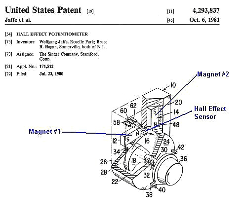
Figure Two: Patent 4,293,837 describes how to build a rotary angle or linear position sensor with a dual
magnet magnetic circuit, but this magnetic circuit can also be used to build a gear tooth position sensor if
one uses a Hall Effect Latch IC or Hall Effect Switch IC in place of the Linear Analog Hall Effect IC.
magnet magnetic circuit, but this magnetic circuit can also be used to build a gear tooth position sensor if
one uses a Hall Effect Latch IC or Hall Effect Switch IC in place of the Linear Analog Hall Effect IC.
Figure One: The basic magnetic circuit that will be used to build a Hall Effect gear tooth
sensor or a Ferrous Object sensor which will detect a passing steel bolt head.
sensor or a Ferrous Object sensor which will detect a passing steel bolt head.
| Page One of Six |
Note: The magnet material used to make the two magnets for this sensor was found at a local
hobby store and were listed as a hot pad or picture hanging magnet. The magnet was fairly
strong and most likely made of some type of bonded Neodymium magnet material. Since the
magnets were made from a bonded plastic material, it was easy to cut and sand the magnets
into the desired shape. (See the drawing in Figure Ten)
By: Robert H. Luetzow 12-05-04