| Page Two of Six |
| Go To Home Page |
Building a Hall Effect Gear Tooth Sensor
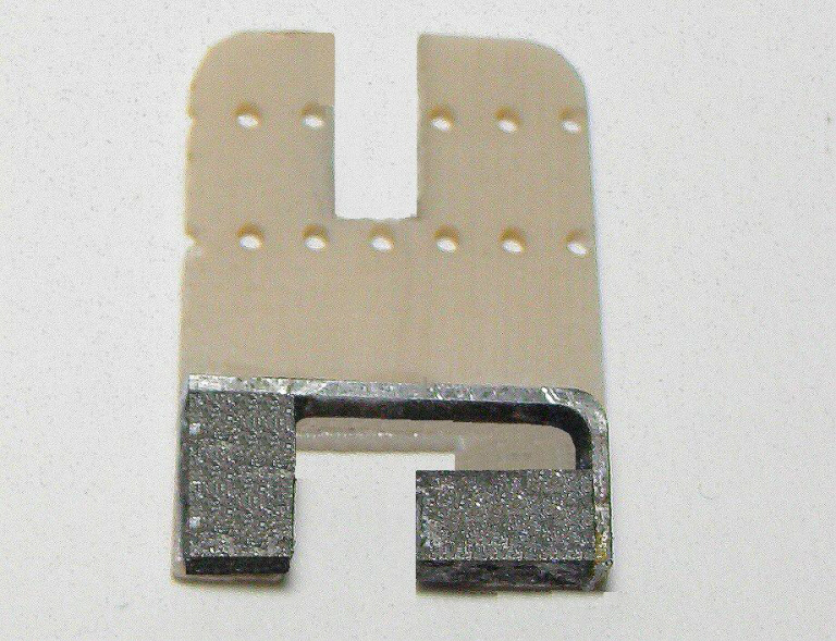
Figure Four: The Hall Effect position sensor assembly
parts.
parts.
Figure Three: This is a picture of the magnetic circuit that is assembled and glued on to a piece of
electronic circuit built-it board. The assembly pole piece can be made from any type of magnetic steel.
The magnetic circuit in the patent does not use a pole piece and the magnetic circuit will work if one is
not used. But using an assembly pole piece to help glue and hold the magnets in position will make
building the magnetic circuit much easier. The air gap between the magnets must be large enough to
permit mounting of the Hall Effect IC. The two magnets were attached to the assembly pole piece using
supper glue. The magnetic circuit assembly was then attached to the circuit board material using five
minute epoxy.

Figure Four: This figure shows the two basic Hall Effect sensor assembly parts. The electronic circuit
board on the left contains the Hall effect IC sensor, the load resistor, and two by-pass capacitors. The
circuit schematic is presented in Figure Eight. The magnetic circuit board on the right has a slot cut in it so
it will fit under the screw and washer on the electronic circuit board. The magnetic circuit board is then
adjusted up or down so the Hall Effect IC sensor will received the correct magnetic bias for the proper
electrical switching characteristics.
Ferrous Object Position
Sensor
Sensor
or a