| Page Six of Six |
Building a Hall Effect Gear Tooth
Sensor
Sensor
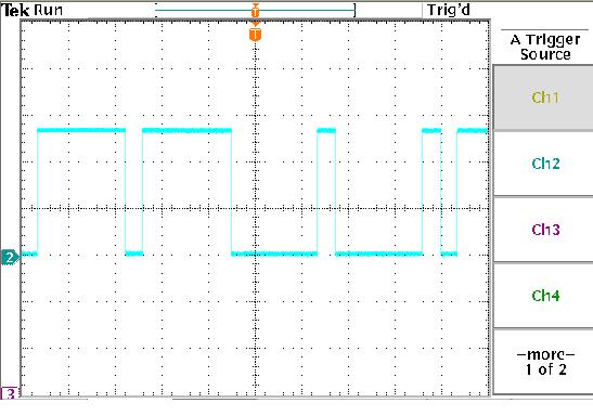
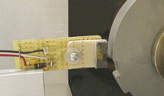
Figure Thirteen: This figure shows the Hall Effect gear tooth sensor mounted on a test
spinner to detect the target wheel gear teeth as they pass by the Hall Effect sensor. The air
gap between the sensor magnets and the target wheel in this picture is .127 Inches. The
oscilloscope is connected to the two wire loops on the circuit board. The scope probe is
connected to the wire loop that is connected to the white wire and the scope ground is
connected to the loop which is connected to the black wire. The waveform that is
generated as the target wheel is spinning is shown in Figure Fourteen.
Figure Fourteen: This is the oscilloscope waveform of the signal generated by the Hall
Effect Sensor as the gear teeth and gear slots pass by the front of the sensor.
Effect Sensor as the gear teeth and gear slots pass by the front of the sensor.
or a
Ferrous Object Position
Sensor
Sensor