| Page Four of Six |
Building a Hall Effect Gear Tooth
Sensor
Sensor

Figure Eight: This is the schematic of the sensor electronic circuit board shown in Figure
Three.
Three.
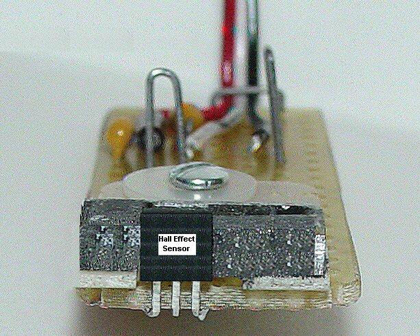
Figure Nine: This is the front view of the Hall Effect sensor assembly showing how the Hall Effect IC fits
between the two magnets. The Hall effect IC leads are bent at a 90 degree angle and soldered to solder
pads on the bottom side of the board. Most Hall Effect ICs all use the same pin-out which looking at
the front of the IC, the left lead is the +Vdc input, the center lead is the Ground lead, and the right lead is
the Signal Output lead, but you should check the actual specification sheet before making any
connections to the Hall Effect IC..
or a
Ferrous Object Position
Sensor
Sensor